29+ 4 to 16 decoder block diagram
The parallel inputs A 2 A 1 A 0 are applied to each 3 to 8 decoder. 3 to 8 Decoder Logic Diagram.

Half Adder Circuit And Its Construction In 2022 Circuit Diagram Diy Electronics Circuit
Draw the block diagram of that decoder Please dont show the logic circuit that has active HIGH inputs.
. The block diagram and the truth table of the 2 to 4 line decoder are given below. A decoder is a combinational circuit constructed with logic gates. Required number of 38 Decoder for 416 Decoder 168 2 Therefore we require two 38 Decoder for constructing a 416 Decoder the arrangement of these two 38 Decoder.
In 21 authors design 2-to-4 3-to-8 and 4-to-16 decoders by using the R-I and NOT gates. The block diagram and circuit diagram is shown below. The block diagram of 4 to 16 decoder using 3 to 8 decoders is shown in the following figure.
See the answer See the answer done loading. Draw a block diagram showing how this decoder. It is the reverse of the encoder.
The new circuit for 3-to-8 decoder presented in 20 uses the Fredkin and DVSM gates. A decoder circuit is used to transform a set of digital input signals into an equivalent. This problem has been solved.
For 2n inputs an encoder circuit gives n outputsThe following figure shows the block diagram of a decoderThis decoder circuit gives 8 logic outputs for 3 inputs. Design a 16-to-4 Encoder with block diagram truth table and Boolean expression. A 4-to binary decoder has 4 inputs and 8 outputs.
Each CML AND gate acts as a 2 to 4 decoder. As a result a total of 5 decoders are required. Electrical Engineering questions and answers.
The 2 to 4 binary decoder has 2 binary inputs and 4 coded outputs. The logical diagram of the 38 line decoder is given below. 416 Decoder has four inputs and sixteen outputs.
But output at a time will be generated by 1 decoder only at a time. Given a 4 to 16 decoder with an enable line. It is convenient to use an AND gate.
H HIGH voltage level. September 1993 4 Philips Semiconductors Product specification 4-to-16 line decoderdemultiplexer 74HCHCT154 FUNCTION TABLE Note 1. The complement of input A3 is.
Engineering Electrical Engineering QA Library - What is meant by 4 to 16-line decoder. The logical expression of the term Y0 Y0 Y2 and Y3 is as follows. Y 3 EA 1A 0.
Just replace the symbol. A and B are the two inputs and the output. It can easily be created by combining two 3-to-8 decoders together and can be used to.
3 to 8 line Decoder has a memory of 8 stages.

74hc154 K1533id3 Led Matrix Led Arduino

4 16 Decoder Using Two 3 8 Decoders Logic Circuit Electronics Circuit

433mhz 4ch Remote Controller Remote New Electronic Gadgets Control

Arduino Audio Save

433 Mhz Rf 8 Appliances Transmitter Circuit Circuit Projects Remote Control Electronic Circuit Projects

Pin On Drone

Pin On Electronic
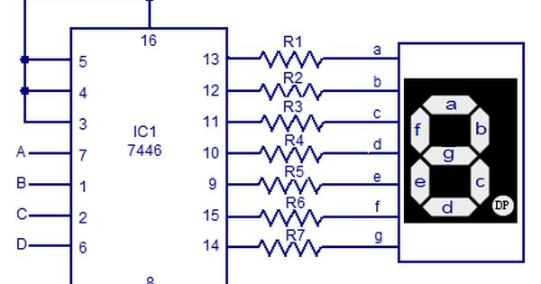
7446 Seven Segment Decoder Driver Circuit Diagram Electronic Circuit Projects Circuit Diagram Electronics Basics

Intel Haswell Microarchitectures Computer Architecture Intel Instruction

Remote Or Transmitter Circuit Circuit Electronic Circuit Projects Remote Control

Bcd Counter Circuit Using The 74ls90 Decade Counter Basic Electronic Circuits Electronic Schematics Electronics Basics

Binary Decoders Circuit Diagram Diagram Circuit

Design Your Own Compact 5v 3 3v Smps Circuit For Embedded And Iot Projects Iot Projects Electronics Circuit Circuit

Pin Diagram Of 8051 Microcontroller With Description Block Diagram Microcontrollers Diagram

P10 Led Matrix Panels 16x32 Led Matrix Matrix Led

In This Article We Elaborately Learn To Make A 2 4ghz 10 Channel Remote Control Switch Circu Circuit Projects Electronic Circuit Projects Electronic Schematics

4 16 Decder Binary To Hexadecimal Decoder For 4 Input Circuit Design Circuit Binary